Why this Blog?

The purpose of creation of this new blog was to add all my work that will solely related to my DIY Solar and wind electricity generation system. I will also add here the adventure of my DIY micro-hydro turbine (PAT) unit that has been planned to be implemented in the beautiful Kalam valley. In the recent past i unintentionally got attraction toward the green energy and studied a lot about.

My last visit to Karachi home was the turning point to divert all my intentions and resources toward getting into hybrid solar+wind electricity system. The 12 hours shedding at Karachi was really a mental shock to me. The 2Hours alternate load shedding scheme was so pathetic that for three nights i had only 6 hours of sleep in total. The Starting/Stopping the generator (located at the third floor) was a real muscular exercise especially the last part of the night.

The ready made solution requires a handsome amount of money. Here i will post my DIY approach to get the job done considering the advantage of being low cost, worth of experience and as per my requirement and quality. I intend to work on both Solar and wind turbine simultaneously so that to give the relief to my family.

Lets see will i have success in this endeavor?


Thursday, December 27, 2012

Dual Axes SunTracker with Advanced Options


Finally i came up with the new efficient algorithm for the dual axes sun tracking system. The tracker is menu based , parameters can be set with 6-keys keypad with following functionalities:


1- Single Axis or Dual Axis control settings
2- 12VDC / 24V DC motor (windshield car motors etc) or Linear Actuator (Peak Current 10Amp)
3- PWM based motor controller. The PWM value is selectable from Menu.(0~100% duty cycle)
4- Return East Options (a- On Limit Switch stoppage based or -b- Time based)
5- User Selectable Tracking Delay
6- Load Sequencing management
7- Dark return Time setting
8- Twilight Time settings (after the twilight Dark return Time started)
9- RJ45 connectors for sensors
10- Sensors sensitivity settings
11- Highly efficient tracking Algorithm
12-Drive Off sun position setting
13-Easy menu driven parameters settings
14- Saving Parameters values in EEPROM
15-Compact and easy to install
16-Northern/Southern Hemisphere Compatible

LCD, Keypad and sensor:


I am still adding much more features as it is micro-controller driven..
Modular type:
1- Main Controller (Price Range 30~45 US dollar)
2- PWM DC Motor Controller (10 ~15 US dollar)
3- Sun Tracking sensors (single axis or dual axis) (5~10 US dollar)
4- 20x4 backlight LCD with control circuit ( 12~15 US dollar)
5- six Key keypad (2 US dollar)
6- Optional controller to sensor wiring

Tuesday, October 2, 2012

Mistakes... I think i am learning new things...

One more addition of foolish blunder in my life 
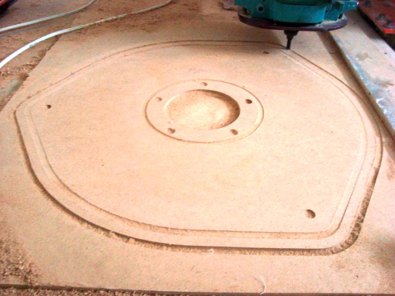
below i posted a CAD drawing snap of the magnetic plate and stator... Something is very wrong in it.. 12 magnets and 12 coils... Its not possible

After casting and painting the magnetic plates and making 9 coils when i assembled the coils around the magnets i feel that i have wide gaps between the coils... Then i consulted the drawing i made earlier, their were 12 coils.. what a nonsense... no way... This should be 9 coils...not more not less...

So i have to destroy the magnetic plates for salvaging the magnets... Now i am going to make new magnetic plates with small diameters...This is a good thing..but why this happen, its still needs to be figured out.. this regularly happens in my life and reminds me i am a human and not a genius.

Back to the drawing board, corrected the entire things... I am posting the improved coil winder picture that made my life easy. It took 40minutes to make 9 coils, each 110turn with 1.5mm dia laminated wire (SWG17)


You can see i am arranging the coil for resin casting. I am using electrical glass tape for high temperature. i know some time the temperature of the coil will be high during high winds and not want to make another blunder by using the simple tape.


In the drawing you can see rectangle magnets, its 3 phase , so if you see closely the purple coils are at the center of magnets. It means they are providing the full voltage at this condition. the other coils are in the middle of high voltage range when the purple coils are at high peak voltage.


PS:
i have made the coils first, then measured the dimensions and reverse engineer the magnetic plates. i think this is the easy way to go.


"Sometimes when you innovate, you make mistakes. It is best to admit them quickly, and get on with improving your other innovations. "

Sunday, September 23, 2012

Test Coil, Country flag and Turbine blades


I made a test coil winder earlier and today i made one coil with 37 turns. I didn't add any varnish coat but the coil is difficult to remove from the fixture 
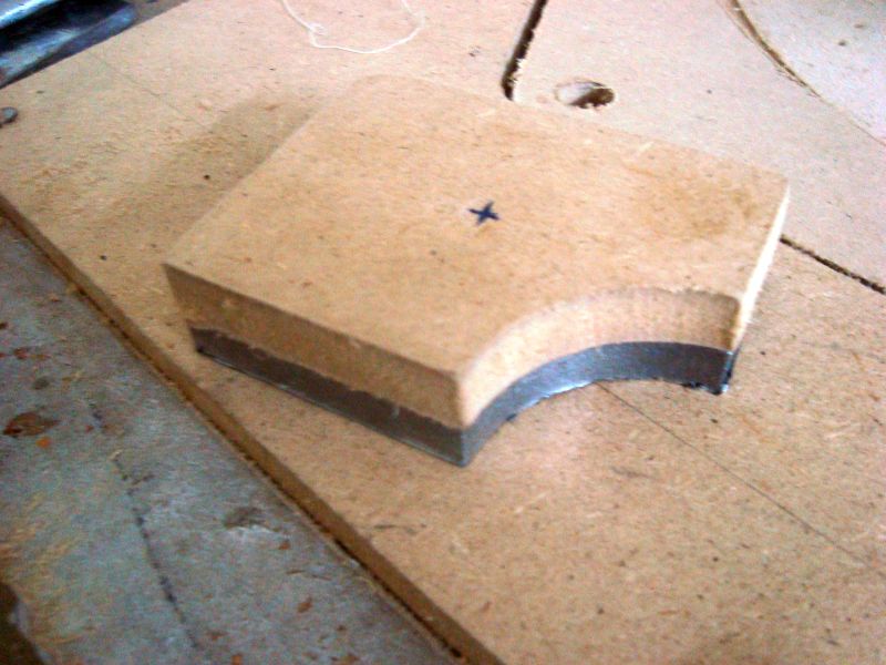
... I shall make another simple jig tomorrow that will ease up removing the coil without destroying it.


"Roman" at cnczone posted a helping post in my thread about Coil winding , following are his words for everybody who need to wind the coils:

"About your coil winding jig, I have done many coils and even worked in an electrical motor shop that had a few commercial coil winders.

Suggestion 1; Put the jig on the end of a portable electric drill (with a speed control) and then it can wind automatically. A lathe is also good if it has a low speed.

Suggestion 2; You can paint the coil with varnish or nail polish every layer as you wind it, which will then be a reliable solid coil when done. However this will stick badly to your coil former. If you made the coil former from polyethelene (like food chopping board) the glue will not stick and you can make solid coils then pop them off the former. You might need a small taper on the middle round part, to slide out of the coil.

The magnetic forces on the windings will be high, so somehow they need to be set in resin or varnish. Otherwise if there is any air in the coil the windings will flex and rub because of the magnetic field and soon wear through the insulation and fail.

If putting a dry winding in resin we would put in a vacuum chamber to make sure the resin goes through the coil and no air is present. It is easier to varnish the coil as you wind it, every layer, so I would go for the polyethelene former and do that. Varnish type is not that important, quick dry nail polish is an acrylic and will be strong and bond well later when you set the hard coil into the former with resin."


I hand rotated the magnetic plates and got 1.5Volts (don't know about the RPM) with single test coil. Tomorrow i shall borrow a stroboscope and will plot a graph between RPM and Voltages. following is the formula to get estimated cut in voltages.

Required Cut in Voltages= VAC(of test coil at cut-in speed) x No. of coils/phase x1.732(multiplication factor for 3 phase)x1.414 (DC conversion factor) - 1.4V (diode drop)


The cut-in speed i shall keep around 150~200RPM. You can see pictures of furling flapper that is turned into flag of my country.

Three PVC blades 6feet each worked out by my brother one year back . The blades are big you can see pen kept on the center blade for comparison.

Friday, September 21, 2012

Wind Mill Charge Controller arrived

At last i received the wind mill charge controller. It took about 15 days to reach at my door step from Hong Kong port :).. It seems very solid and i have also recieved the software CD to monitor various parameters of the wind turbine.
I also completed the furling tail flapper.


Friday, September 14, 2012

Birthday of My son


Coil Winder Jig completed

I have completed the coil winding jig. Meanwhile, i purchased the copper laminated wires SWG 17 number for making coil. The price of laminated wire per Kg is 11US dollar. I purchased 5.5Kg of laminated wire.


Monday, September 10, 2012

Fiber Glass Resin Casting of magnetic Plates

Yesterday, after two failed attempts of fiberglass resin casting of magnetic plates i at last succeeded.


Friday, September 7, 2012

Alternator mount Frame and Furling completed

Today i have completed the Alternator mount frame and furling design. I cut the 55 degree triangular jig which make the whole assembling process very easy and timely.


Thursday, September 6, 2012

Beware of Advertisements- Chinese Wind Turbines

Recently I spent some time going over ads for micro turbines, and there's lots of interesting claims out there. So before anybody parts with their hard earned cash some wind math is in order.

A case in point is an ad for a micro turbine:
"We build these wind turbines to provide 1200watts of power. They are suitable for charging 12/24/48 volt battery systems....in winds over 4-5mph (6.4-8kph or 1.7-2.2ms)...Brand new 24” (.61m) blades."

Wow, 1.2kW from a 48" (1.22m) diameter blade. Unless you live in a wind tunnel you'll never see that kind of an output.

The most energy you can extract is 59.3% of the total kinetic energy contained in the wind. Most small scale turbines operate much lower then that, while industrial turbines approach it, but still can't get there.

According to the Bertz co-efficient you would need a sustained wind of 27mph (43kph or 11.9ms) to get 1200w from a 48" (1.2m) or 4ft blade (Wind turbine diameter=8ft). To come to this number we need to use some wind math;
---------------------------------------------------------------------------------------------------------
First we need the swept area of the rotor;
Area = π x (blade diameter x blade diameter) / 4
Using the above ad - 3.1416 x (1.22 x 1.22) / 4 = 3.1416 x 1.4884 / 4 = 1.17m2
---------------------------------------------------------------------------------------------------------
Power in watts = .5 x air density x swept area x wind velocity3
Where - air density (@ sea level) = 1.23kg/m3
            - swept area in m2
            - velocity in meters per second
So.......... .5 x 1.23 x 1.17 x 5.5ms3 (5.5ms is my areas average wind speed)
               .5 x 1.23 x 1.17 x 166.37 = 117.91 watts
--------------------------------------------------------------------------------------------------------------------------
Now lets try doubling the blade area;
.5 x 1.23 x 2.34 x 5.5m/s3 = .5 x 1.23 x 2.34 x 166.37 =  239.42 watts
*Doubling the blade diameter roughly doubles the power output.
--------------------------------------------------------------------------------------------------------------------------
Now lets use the original swept area and double the wind speed;
.5 x 1.23 x 1.17 x 11m/s3 = .5 x 1.23 x 1.17 x 1331 =  957.72 watts
*Doubling the wind speed roughly increases 8x the original power output. Yet we're still not at the 1200watts from the original ad.
--------------------------------------------------------------------------------------------------------------------------
Using 43kph wind speeds;
.5 x 1.23 x 1.17 x 11.95m/s3 = .5 x 1.23 x 1.17 x 1706.49 = 1227.9 watts
Wind speeds like this happen very rarely in most areas of the world.


Below is a spreadsheet showing output at different wind speeds using the above 3meter (9ft) diameter wind mill.

Wednesday, September 5, 2012

More CNC and Metal work

Today i machined the template for marking the position of Stator Holes on the structural frame. This template shall also be used for Resin casting. Moreover, the metallic structure for mounting the wheel hub and magnetic plate is also fabricated. Some snap shots of today's work.


 The picture shows an Antique drill machine in local workshop where the structure being fabricated.

Tuesday, September 4, 2012

Precision Parts and Progress Updates

As the drawing development in progress so the parts coming out from my home made CNC machine.


Some MDF template along-with actual metallic parts.
 
You can see how accurate  the MDF part produced with my home made CNC router compared to a metallic part produced with a precision industrial CNC machine.

Saturday, September 1, 2012

CNC Machining of Coil winder

Today completed the coil winder on my CNC machine.


the CNC machining process.


 Checked the fitup of the coil winding mockup on the magnets and its perfect.

Wind-Solar Hybrid Charge Controller on its way

Today i purchased the Wind Solar hybrid charge controller with following parameters:


Rated Battery Voltage
24V
Rated Wind Turbine Power
600W
Wind Turbine Maximum Input Current
40A
Wind Turbine Maximum Input Power
1000W
Unload Voltage(factory default)
28V
Unload Current(factory default)
25A
Rated Solar Power
300W
Battery Over Discharge Voltage Shutoff
22V
Battery Over Discharge Recovery
24V
Output Protection Voltage
32V
Display Mode
LCD
Display Parameters
Wind Turbine Power, Wind Turbine Voltage, Wind Turbine Current, PV Voltage, PV Charge Current, PV Power, Battery Voltage,
Over Voltage, Under Voltage, Over Load, Short Circuit, Night. Etc

Friday, August 31, 2012

CNC Mold Machining for magnetic plates Resin Casting

Today i CNC machined the molds out of 12mm thick MDF for resin casting of magnetic plates.The tool used was 8mm end mill at 70inch/minute using 3mm per pass depth of cut. The mold machining took 35minutes on the CNC router. The cast resin will help bounding the magnet with the CS plates so that the magnets stay at high RPM.


 Hole drilling started on my home made CNC machine.

 and the rest of the pictures are below.
and the magnetic plate fitted exactly in the MDF mold as desired.